How to create a base module
This tutorial shows you the preferred way to make a class from a collection available in OpenSCAD.
This assumes that you have already a module available that takes a number of parameters as input and builds the part that the class describes.
If not you have two options. Either you learn OpenSCAD and write such a module yourself.
Or you try to find out if someone else has done this already. There are a number of sites where a lot of scad code is published:
However, to use code written by someone else, you need to make sure that there are no licensing problems. I wrote about licensing in BOLTS here. If the code has no licensing information or is published under a incompatible license, you can try to contact the author and ask him to dual-license with a license that allows inclusion in BOLTS.
This tutorial will illustrate the process using the example of the pipe
collection with a pipe module that lives in a file called pipe.scad:
/* Pipe module for OpenSCAD
 * Copyright (C) 2013 Johannes Reinhardt <jreinhardt@ist-dein-freund.de>
 *
 * This library is free software; you can redistribute it and/or
 * modify it under the terms of the GNU Lesser General Public
 * License as published by the Free Software Foundation; either
 * version 2.1 of the License, or (at your option) any later version.
 *
 * This library is distributed in the hope that it will be useful,
 * but WITHOUT ANY WARRANTY; without even the implied warranty of
 * MERCHANTABILITY or FITNESS FOR A PARTICULAR PURPOSE.  See the GNU
 * Lesser General Public License for more details.
 *
 * You should have received a copy of the GNU Lesser General Public
 * License along with this library; if not, write to the Free Software
 * Foundation, Inc., 51 Franklin Street, Fifth Floor, Boston, MA  02110-1301  USA
 */

module pipe(id,od,l){
    difference(){
        cylinder(r=od/2,h=l,center=true);
        cylinder(r=id/2,h=l+1,center=true);
    }
}
Putting the scad file to the right place
The file with the module should be moved to a subdirectory of the openscad directory which is named after the collection id to which the part belongs. If this directory does not exist, create it.
So in the case of the pipes collection pipe.scad is now in the directory
openscad/pipes relative to the BOLTS root folder.
Write the base file
This collection directory must also contain the base file for this directory. The base file provides BOLTS with all the information it needs to know about the files in a collection directory, it is a kind of manifest file. It contains a list of sections (more precisely base file elements), each describing one file.
For the pipes collection the base file is openscad/pipes/pipes.base and has
the following content:
---
- filename: pipe.scad
  type: module
  author: Johannes Reinhardt <jreinhardt@ist-dein-freund.de>
  license: LGPL 2.1+ <http://www.gnu.org/licenses/lgpl-2.1>
  modules:
    - name: pipe
      arguments: [id, od, l]
      classids: [genericpipe, din11850range2]
  source: own work
...
The type field indicates, that this file contains one or more OpenSCAD
modules. The author field gives the author of pipe.scad and contact
information. In the license field the license of pipe.scad is indicated and
then follows the list of modules that are contained in the file.
In the case of pipe.scad there is only one module called pipe. The
arguments field gives the parameters that need to be supplied to the module.
The parameters must be a subset of the parameters of the class as it is
defined in the blt file.
The classids field contains a list of classids which this module can
represent. Be careful, that the parameter names and meanings for all classes
in this list must be the same, otherwise the some parameters can not be found
for some classes.
There is the possibility to add an optional source field which allows to give
information about the origin of the file. If there is a URL from which this
file was downloaded, this can be included here.
Testing
Now it should be tested that the newly added part really works. This is most conveniently done using the utility script:
./bolts.py export openscad
./bolts.py test openscad
This will fire up a OpenSCAD instance with the module search path set appropriately, so that typing
include <BOLTS.scad>

DIN11850_Range_2("10",1000);
should give you a pipe with nominal diameter 10 and 1m length.
Adding connectors
Connectors simplify the positioning of parts in OpenSCAD, but require a bit of preparation. Three things need to be added: A function for the connectors and a entry in the base file and drawings for the documentation.
The function is added to the .scad file, and calculates the position and
orientation for the various connector locations from the parameters of the
model. It returns a list containing as first element the origin of the
coordinate system in terms of global coordinates, as second element a list with
two directions for the first and second direction of the connector. In case the
direction is unknown, the function should return "Error".
For the pipes ths function could look like this:
function pipeConn(l,location) =
    (location == "front-in")  ? [[0,0,-l/2],[[0,0,1],[1,0,0]]] :
    (location == "front-out") ? [[0,0,-l/2],[[0,0,-1],[-1,0,0]]] :
    (location == "back-in")   ? [[0,0,+l/2],[[0,0,-1],[-1,0,0]]] :
    (location == "back-out")  ? [[0,0,+l/2],[[0,0,1],[1,0,0]]] :
    "Error";
Here only the origin of the connector depends on the length of the pipe, but for other locations other parameters might be required. The function can make use of all parameters that are available to the geometry modules in addition to the location, and the order in which these are passed to the function is not relevant.
To tell BOLTS about this and things like the available selection of locations available. This is done by a additional field in the base file. The entries are selfexplanatory, so here is the content of the base file with the connector infos:
---
- filename: pipe.scad
  type: module
  author: Johannes Reinhardt <jreinhardt@ist-dein-freund.de>
  license: LGPL 2.1+ <http://www.gnu.org/licenses/lgpl-2.1>
  modules:
    - name: pipe
      arguments: [id, od, l]
      classids: [genericpipe, din11850range2]
      connectors:
        name: pipeConn
        arguments: [l,location]
        locations: [front-in, front-out, back-in, back-out]
  source: own work
...
This is a good time to test again. You can use the utility script like shown earlier. Make sure all connectors are where they should be and that this remains the case when you use a range of parameters.
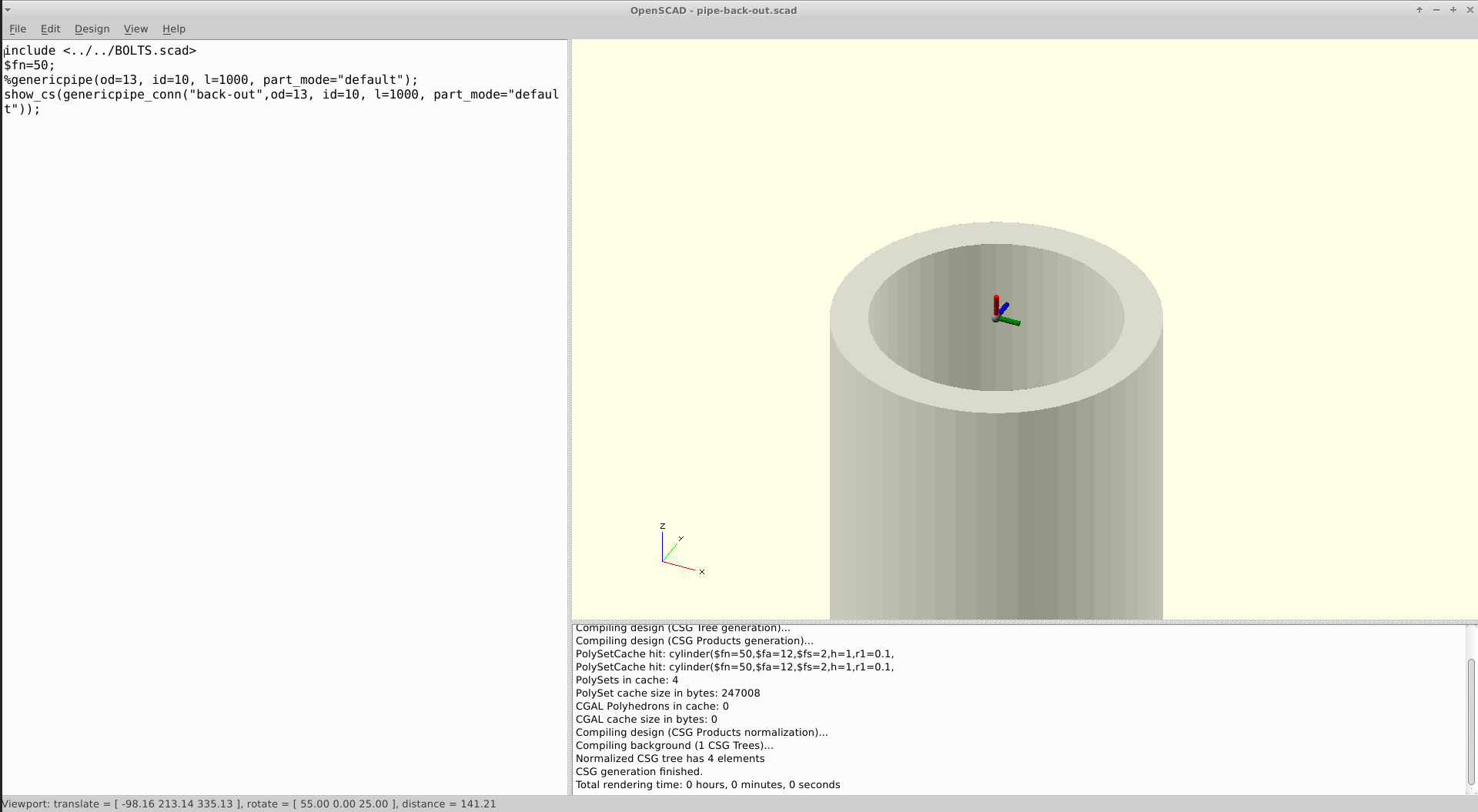
The final thing to do is create drawings for the connectors to visually show their location for easy reference. The utility script can do most of the heavy lifting, by creating OpenSCAD scripts for each location that shows the part together with the connector there.
./bolts.py connectors
This results in a directory called connectordrawings in the output directory.
It contains BOLTS for OpenSCAD and a directory called scad that contains scad
files for all classes with connectors that have no drawings. All that remains
to do is to load these scripts into OpenSCAD, find a good angle and export a
png using Design->export as image.... Make sure that it is easy to understand
from the picture where the connector is located on the part, and how it is
oriented.The images go into the pipes subdirectory of the drawings folder.
The final step is to add entries to the base file in this folder to tell BOLTS
about all the drawings. Here is an example how it looks for the front-in
connector:
- filename: pipe-back-in
  author: Johannes Reinhardt <jreinhardt@ist-dein-freund.de>
  license: CC0 1.0 <http://creativecommons.org/publicdomain/zero/1.0/>
  type: drawing-connector
  location: back-in
  source: own work
  classids: [genericpipe,din11850range2]
You should add your name as author. The license should be chosen to CC0, as
this makes things easier. type must be drawing-connector.
To check that everything went fine, you can use
./bolts.py tasks
and make sure that the classes you have been working on are not listed anymore
with Missing Connectors and Missing Drawings.
Next steps
You might want to contribute this part to BOLTS, so that every user can profit from your efforts.